02/08/18
While designing a synchronous electric machine or a whole electric drive it is often useful to estimate its external characteristics \(T(\omega)\). Such plot can be used to predict practical speed range of a drive given its maximum voltage and current limits or conversly to find required parameters of the inverter for given speed range.
Sine wave machines can be accurately analyzed using phasor diagrams of first harmonics to estimate external characteristics analitcally while square wave machines would require analysis of higher number of harmonics. In general in Surface Permanent Magnet (SPM) machines electromagnetic torque is proportional to the current in q-axis, \(I_q\) (the current in phase with the back-EMF) and the amplitude of back-EMF, \(E_q\) is proportional to the angular speed of the rotor. In such synchronous machines only q component of the supply voltage \(V\) causes flow of \(I_q\) current in windings and as any machine have some inductances in each \(L_d\) and \(L_q\) axes when speed is non-zero, the supply voltage phasor angle would be shifted proportionally. In case of the SPM the relations is simplified as both q and d-axis inductances and thus the reactances \(X_d\) and \(X_q\) are equal.
 synchronous motor.")
The relationship \(X_s=X_d=X_q\) holds because magnet permeability is almost identical with air permeability and therefore form windings point of view the distance between rotor yoke and stator in SPM does not change.
\[ E=jE_q\]
Back-EMF \(E_q\) is always aligned with q-axis between each consecutive rotor poles, where (considering only first harmonic) the rate of change of the flux is at its maximum. At some operating speed \(V_q=Vcos(\phi)\) becomes smaller than \(E_q\) plus ohmic voltage drop at \(R\) and the torque producing current in q-axis cannot flow. To counter act this the current can be pushed into the machine by adjusting phase shift angle \(\phi\) of the supply voltage which decreases the back-emf. This way the current injected into d-axis weakens the physically rotor field amplitude created by its magnets and therefore its derivative in respect to time - the induced voltage \(E_q\). When current Iq has negative values the machine operates as a generator.
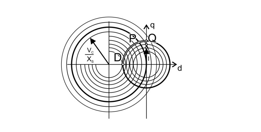
As torque \(T=k_T I_q\), the external characteristic of a machine can be predicted by finding \(I_q\) current at each point of operation. The magnitude of current is limited by inverter current limit \(I_c\) and maximum current density in the machine windings (machine cooling capability), similiarly the inverter voltage is limited by \(V_c\) close to the DC-link voltage. Demagnetising or magnetizing current \(I_d\) is limited by the magnets BH characteristics at each given temperature as well as desired machine efficiency. By observing the phasor diagram two eqations describing the limit circrles can be written as
\[ I_d^2+I_q^2=I_c^2\]
and
\[ V_d^2+V_q^2=V_c^2\]
Then using Ohm’s law voltage circle can be converted to the second circle equation describing current. When \(Z_s=R+X_s\) then
\[ {I_d}^2+ \left( \frac{I_d+E_q}{Z_s} \right)^2= \left( \frac{V_c}{Z_s } \right)^2\]
These two equations of the currents can be plotted on one plane describing limits of loci as the one shown below.

Where \(E_{q0}/X_{s0}\) is constant which can be calculated at one particular speed \(\omega\) (neglecting saturation effects) or computed using inductance and electric constant \(k\).
\[ \frac{E_{q0}}{X_{s0}} =\frac{\omega L}{\omega k}=\frac{L}{k}\]
It is interesting that IPM and other machines in which \(X_d \neq X_q\) these loci are represented by ellipses depending on amplitudes of these reactances.
Using this technique of current loci representation torque can be easily found converting \(I_q\) to electromagnetic torque. The transformed equation describing \(T(\omega)\)
\[ T(\omega)=Re \left( k_T \sqrt{I_c^2 - \left( \frac{Z_s}{2E_q} \left( \frac{V_c^2}{Z_s^2} - I_c^2 - \frac{E_q^2}{Z_s^2} \right) \right)^2 } \right)\]
The presented formula is used to estimage an SPM axial-flux machine characteristics. The last plot shows what would happened if the phase inductances \(L_{ph}\) would be very small to zero and while it was used to check the calculations it also ilustrates influence of phase inductance \(L_{ph}\) amplitude on the machine performance. As can be observed high inductances dramatically decreases speed range at high electrical frequencies, therefore to extend speed range of an electric motor the inductance should be minimized up to the point at which high freqencies created by PWM are still filtered sufficiently.


The described analysis method can be used for all synchronous machines. Moreover analysisng the whole drive composed of an electric motor and a inverter with this and similiar methods at first steps of the design can help improve the system performance, efficiency and minimize costs of the components by choosing the best solutions.